


Trends above and below ground, and what they demand from the components inside
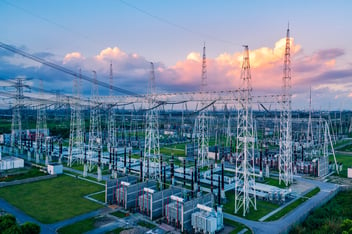
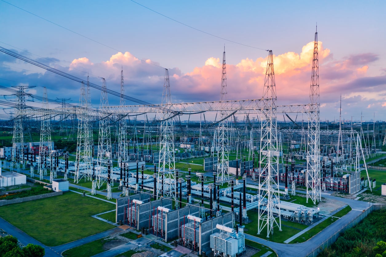
For most of the last century, the substation was the least interesting part of a power project. Generation got the headlines, transmission corridors got the lawsuits, and the substation sat quietly in a fenced gravel yard doing the same job it had done since the 1950s. That has changed. Today the substation decides how fast everything else gets built.
Electricity demand is growing at the fastest sustained rate in a generation. The IEA projects 3.6% average annual global growth from 2026 through 2030, roughly 50% faster than the average across the previous decade, with global consumption reaching about 30,700 TWh by 2027. In the United States, close to half of the increase traces to data centers.
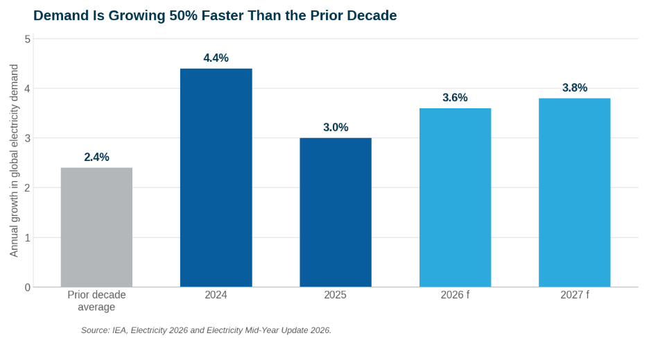
The supply side has not kept pace. More than 2,500 GW of renewable, storage, and large-load projects sit stalled in grid connection queues worldwide. Planning, permitting, and building new grid infrastructure takes five to fifteen years. Building the generation or the data center that needs it takes one to five. Annual grid investment sits near $400 billion and has to rise roughly 50% by 2030 just to keep pace.
A Five-Year Wait for a Steel Box
The sharpest version of the problem shows up in lead times. Before 2020, a large power transformer arrived in roughly 24 to 30 months. Today the wait runs three to five years, and high-voltage substation equipment sits at the long end of that range. US transformer prices have climbed 79%, and manufacturers describe the current environment as a supercycle driven by industrial electrification, renewable integration, and AI data center growth arriving at the same moment.
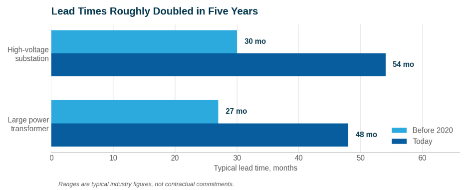
Typical equipment lead times before 2020 versus today.
Hitachi Energy has committed $1.5 billion to transformer capacity inside a $9 billion program, and 92% of data center leaders now name grid constraints as the top factor limiting their growth. Grain-oriented electrical steel, bushings, and skilled engineering labor are all constrained at once. Capacity is being added, but a transformer factory takes three to four years to build.
Where the Money Is Going
Grid investment is climbing everywhere and concentrating in a handful of markets. The United States and China are each nearly doubling their annual grid investment by 2027, making them the two largest markets in BloombergNEF's forecast. Germany is more than tripling its investment by 2027 and stands as the largest European grid investor.
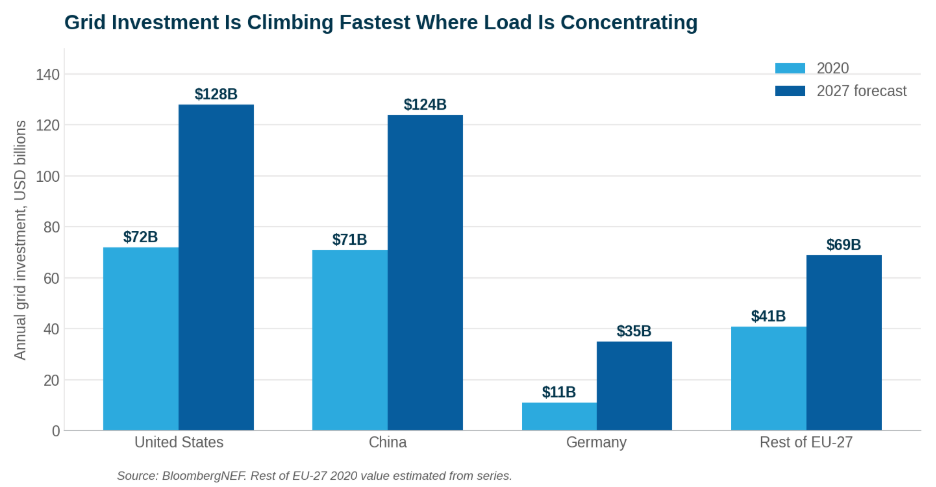
Annual grid investment by market, 2020 versus 2027 forecast. Source: BloombergNEF.
Looking further out, $5.8 trillion of cumulative grid investment is forecast between 2026 and 2035, with roughly $700 billion of that going to digital grid capex. Transmission investment is growing at nearly twice the rate of distribution, and BloombergNEF attributes that growth specifically to long-distance connections, new substations, and HVDC projects.
What a Substation Is Becoming
The substation was a voltage-changing node in a one-way system. It is becoming a control point in a bidirectional, inverter-dominated one: hosting storage, providing dynamic reactive support, managing power quality, isolating faults in milliseconds, and increasingly serving a single customer whose load profile no legacy planning model anticipated.
Five technology shifts are driving that change, and all five are in commercial procurement today rather than in demonstration.
Sulfur hexafluoride is on the way out. SF6 carries a global warming potential of 24,300. EU rules began phasing out medium-voltage SF6 switchgear in January 2026, with a complete ban on new sales by 2031. The replacements already run at transmission voltage: the first 145 kV gas-insulated switchgear insulated with clean air, a nitrogen and oxygen mixture with zero global warming potential, and a 420 kV clean-air pilot on the Belgian transmission network. SF6-free 110 kV substations are contracted for Berlin, one of the largest urban gas-insulated networks in Europe. For North American utilities the open question is timing, not direction.
Copper is going next. IEC 61850 fiber replaces hard-wired copper between the yard and the control house. Low-power instrument transformers replace conventional current and voltage transformers. One reported figure puts the saving at over 5 tonnes of material and hundreds of metres of cable per gas-insulated bay.
Protection is becoming software. Platforms that consolidate multiple protection and automation applications onto common hardware let operators add substation bays through software rather than hardware. Virtual protection and control has moved from research topic to procurement category.
Solid-state conversion has arrived. Silicon carbide devices rated 3.3 to 15 kV operate directly at distribution voltages, where silicon required large series stacks and complex voltage balancing. The result is roughly 40% less footprint and three to five points of conversion efficiency. Capital has followed, and the constraint now is cost, standards, and utility comfort with a device that has no long operating history at scale.
Factories are replacing construction sites. Prefabricated power skids cut deployment time by 30% or more and cost by over 15%, and substation fabrication runs in parallel with the building it serves. At the far end of that trend, some large loads skip the grid connection entirely. On-site generation paired with skid-mounted electrical modules claims two to four years off launch timelines, and the 800 VDC reference architecture converts 13.8 kV AC straight to rack-level DC at the facility perimeter.
Above Ground or Below
Siting used to be an aesthetics argument. It is now a land, permitting, security, and thermal decision, and all four now favor going smaller, sealed, and often below grade.
Gas-insulated designs cut footprint by roughly 70% against an open-air yard, which is exactly why they are becoming the default wherever land is scarce or contested: dense urban cores, coastal sites, and any jurisdiction moving toward SF6-free mandates. Beyond that are the underground options. Eversource's Greater Cambridge Energy Project puts roughly 35,000 square feet of substation about 105 feet below the surface. Singapore's SP Group operates a 230 kV underground substation built with Tokyo utility experience. National Grid's London Power Tunnels programme runs roughly 60 km of deep tunnels linking substations at 400 kV and 132 kV. T&D World projects that half of new distribution will be underground by 2040.
Security reinforces the same direction. NERC's E-ISAC counted more than 3,500 physical security breaches in 2025, up from 2,800 two years earlier. Concealment, fewer access points, and hardened structures all argue for putting critical equipment out of sight.
Every Change Points to the Same Direction
Read those trends together and one physical consequence falls out of all of them. Gas insulation removes volume. Solid-state conversion removes more. Sealed and buried enclosures remove natural ventilation entirely. Higher switching frequencies raise loss density at the same moment the box shrinks.
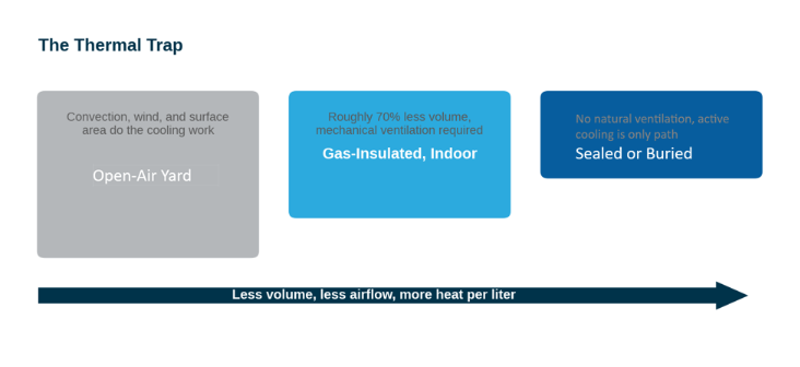
Each step toward a smaller substation removes cooling capacity.
Heat stops being an HVAC line item and becomes a component specification. Every size reduction that justified the compact design also removed the cooling path that made the old design work.
What Breaks First
Capacitors sit at the intersection of every trend above. They occupy the hottest part of a shrinking enclosure. They carry the ripple current that inverter-based generation and fast-switching loads create. And conventional designs derate above 85°C, which forces oversizing, which defeats the footprint argument that justified the compact design in the first place.
The failure mode is rarely dramatic. It is drift, derating, and a maintenance interval that quietly gets shorter every year, in exactly the locations where maintenance access costs the most.
What Capacitors Have to Become
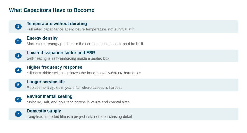
Seven requirements for capacitors in compact, sealed substations.
The market has already noticed. DC-link capacitor volume is expected to roughly double by 2035, and the high-temperature film segment is growing faster than the film capacitor market overall. Industry analysis states the requirement plainly: manufacturers must push dielectric temperature limits beyond 125°C without sacrificing volumetric efficiency.
That requirement now applies across every capacitor function in a substation. Shunt banks for power factor correction face higher ambient and more harmonic exposure. Filter capacitors face rising distortion from inverter-dominated grids. STATCOM and SVC DC-bus capacitors face fast switching and continuous duty. HVDC converter stations face voltage ripple over long cable runs. Solid-state transformers combine all of it at once, hot and high-frequency and compact.
Which Capacitors, and Where
Not every capacitor in a substation carries the same stress, and the fix depends on exactly where in the system it sits. Peak Nano's application mapping across substation designs breaks that exposure into a few distinct categories.
Power factor correction and harmonic filtering see it first. Shunt banks used for power factor correction face more harmonic exposure, tighter space, and higher ambient temperature as they get packed into gas-insulated and modular enclosures. Filter and tuned-bank capacitors used for harmonic filtering face rising distortion levels as inverter-dominated generation displaces the clean sine wave conventional grids used to deliver. Series capacitor banks used for series compensation are seeing longer transmission corridors and more dynamic loading as utilities push more power through existing rights-of-way instead of building new ones.
Reactive support and converter stations run harder. STATCOM and SVC DC-bus capacitors, which provide dynamic reactive support, operate under fast switching, high ripple, and continuous duty at the same time. HVDC converter stations already rely on film capacitors as the incumbent technology at utility scale, managing voltage ripple across cable runs that can stretch for hundreds of kilometers.
Solid-state and 800 VDC architectures are the hardest cases. Solid-state transformers combine every stress on this list at once: their DC-link capacitors, seated between cascaded switching cells, run hot, at high frequency, under high ripple, inside an enclosure with none of the volume a conventional design allowed. Eight hundred volt DC distribution, feeding facilities like AI data centers directly, is a volume category for DC-link and bus capacitors that did not exist five years ago.
Wide-bandgap switching and storage are catching up fast. Snubber capacitors tied to silicon carbide and other wide-bandgap devices are the fastest-growing sub-segment in the capacitor market as SiC adoption scales, and DC-link capacitors for grid-forming inverters and battery energy storage systems are following the same deployment curve as storage itself.
The common thread across all of it is that the operating envelope moved and the capacitor did not get a vote. Whatever function it serves, it now runs hotter, in less space, with more ripple current, and with a maintenance interval that has to stretch rather than shrink. That is the specific list of problems NanoPlex film was built to answer.
Where NanoPlex Fits
NanoPlex™ LDF low dissipation factor films hold full rated capacitance to 135°C with no derating, shrinkage, or performance loss, and last up to 5x longer under thermal and electrical stress. Ultra-low ESR cuts ripple by 40% and holds total harmonic distortion below 3%. The films are hermetically sealed and chemically resistant for vault and coastal environments, and they drop in without retooling or redesign.
NanoPlex HDC high dielectric constant films deliver 4x energy density in the same footprint, enabling capacitor banks up to 50% smaller and 30% lighter. That is the answer to compact, modular, and space-constrained designs where adding units is not an option.
Both are 100% U.S.-engineered and manufactured with allied-sourced materials, against a market where over 70% of capacitor film is imported. For utilities and OEMs planning grid infrastructure with 30-year service lives, supply chain certainty belongs in the specification alongside the electrical requirements.
Three Things to Do This Quarter
Audit the thermal envelope, not just the electrical one. Measure actual enclosure temperature in your most compact assets and compare it against the derating curve of what is installed.
Separate schedule risk from cost risk in procurement. Modular and prefabricated approaches often price similar to site-built while removing years of schedule exposure.
Write the component specification for 2030, not 2015. Temperature without derating, dissipation factor, service life, and domestic supply belong in the specification, not on the exception list.
Request a NanoPlex sample kit for in-house qualification, compatibility testing, and grid-level performance validation.
NanoPlex film specifications are characterized per ASTM D150, D149, D638, and D792, and JIS K7133. NanoPlex LDF and NanoPlex HDC are distinct film families; specifications are not interchangeable.